Signals Form Smooth Continuous Waves Unlike Square Digital Waves


It's finally summer! You and your family are on a cross-country road trip. You have the radio cranked up, and you're all singing along to your favorite song. You drive through a tunnel, and the music stops. If you're listening to a local radio station, the music will turn to static, but if you're listening to satellite radio, the music will completely go silent. Radio, whether satellite or over the air, is transmitted as a signal that is interpreted by your device. If you're listening to satellite radio, the signal is digital , but if you're listening to broadcast or "over the air" radio the signal is analog . In the following activities, we will learn more about the features of digital and analog signals by simulating how these two types of signals are transmitted and used to store information.
Analog Vs. Digital Signals
Digital and analog signals are transmitted through electromagnetic waves . Changes in frequency and amplitude create the music you listen to or images that you see on a screen. Analog signals are composed of continuous waves that can have any values for frequency and amplitude. These waves are smooth and curved. Digital signals, on the other hand, are composed of precise values of 1s and 0s. Digital waves have a step-like appearance.
Analog signals are prone to distortion because even slight errors in amplitude or frequency of the wave will change the original signal. Digital signals are a more reliable form of transmitting information because an error in the amplitude or frequency value would have to be very large in order to cause a jump to a different value.
| Analog | Digital |
|---|---|
| Signals are composed of infinite possible values. | Signals are composed of only two possible values: 0 or 1. |
| Sound signals can vary smoothly in volume and pitch. | The signal leaps from one value to another. |
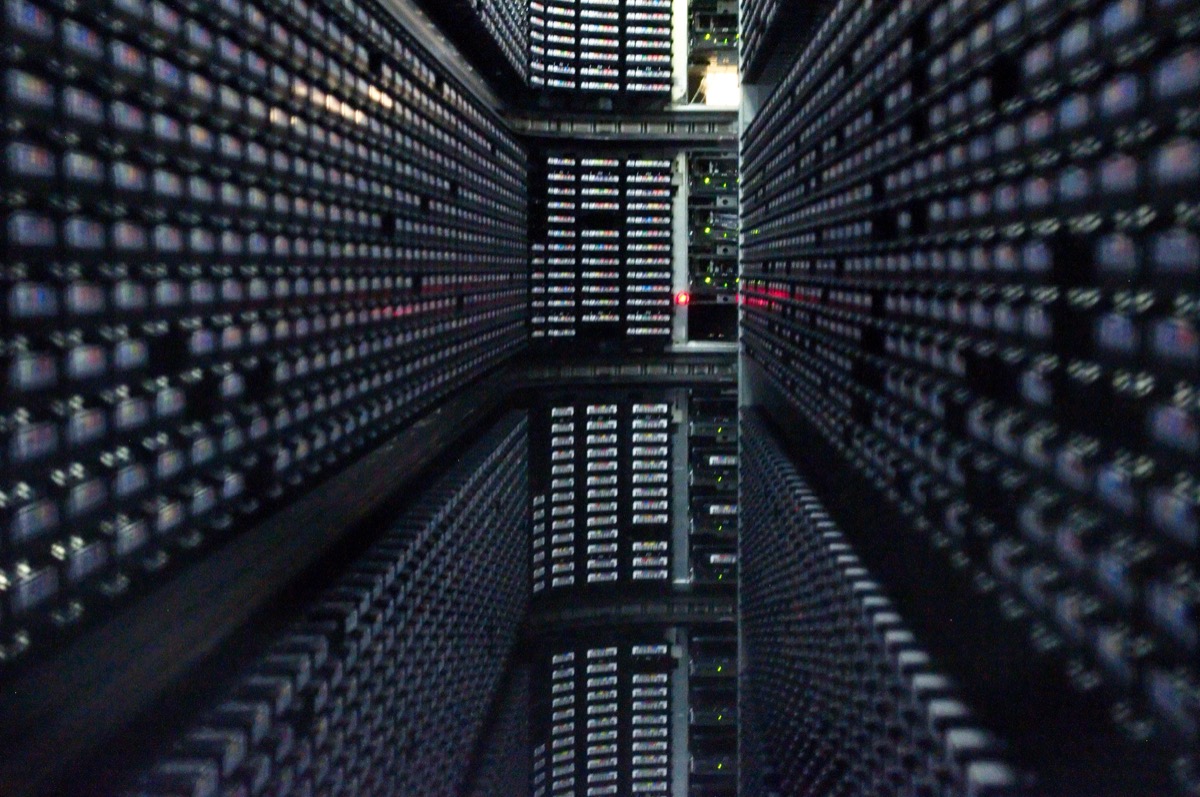
These two signal types are used to communicate and send information in many different forms, like radio transmission, text messages, phone calls, streaming videos, and playing video games. They also can be used to store information and data. Data storage is used by large companies like banks to store records. Individuals also use data storage for personal use, like storing files, photos, games scores, and much more.
Learn more about the features of data storage in the Science Friday series, File Not Found .
Related Article
Ghosts In The Reels
Activity 1: Communication Signal Simulation
In this activity, students will simulate sending analog and digital signals, similar to the child's game of "telephone," but in the form of copying a series of drawings. This activity models the key differences between digital and analog signals in their resolution and signal fidelity. Students will perform two simulations: one simulating multiple transmissions of an analog signal, and one simulating multiple transmissions of a digital signal.
Analog images are composed of rounded lines to represent that analog waves can have infinite values.

Digital images are composed of straight lines that follow the grids on the handout representing how digital signals are composed of quantized values.

Materials
— Scissors
— Tape or glue
— A black pen or fine tip marker (students should not be allowed multiple attempts to recreate the image)
— Communication Signal Simulation Drawing Pages.
— One copy of each of the 5 digital and 5 analog aliens per table (one alien type per human) from theCommunication Signal SimulationDrawing Pages
Teacher Set Up
- Organize into groups of five in a circle around a table. (Five is the number of aliens provided in the set, and also provides optimum opportunities for students to draw the assigned aliens.)
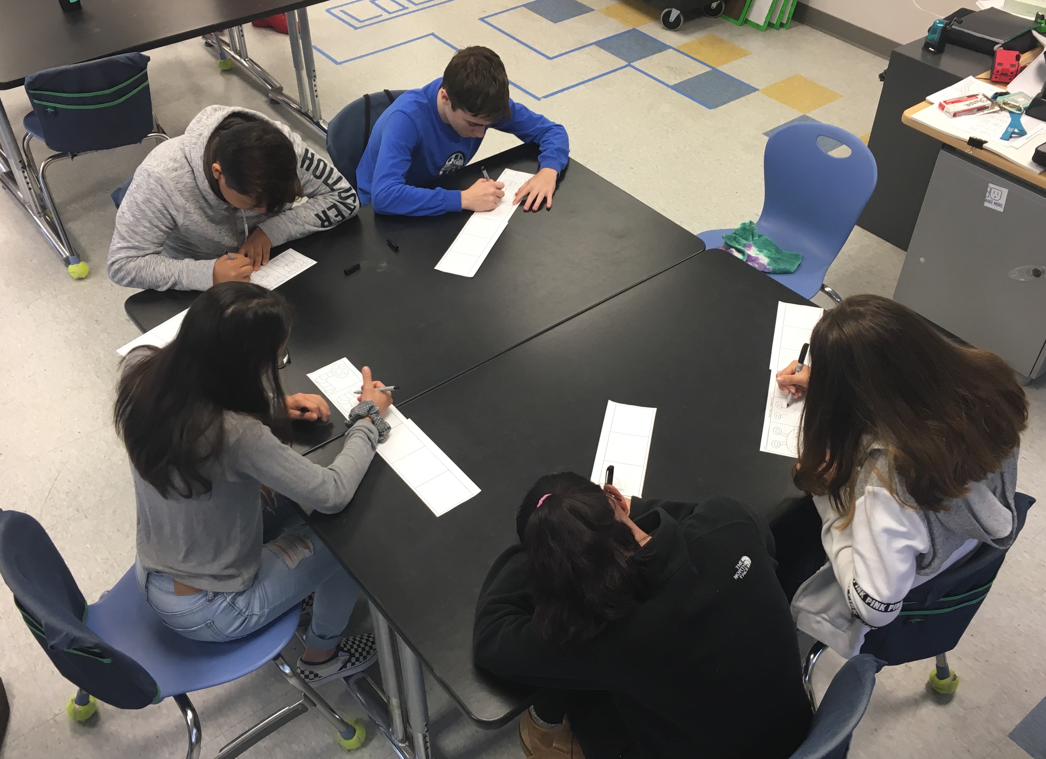
Arrange students in groups of five. Credit: Andrea LaRosa - At each table, give each student a different analog alien page. Hold the digital versions until later. There are five different alien drawings. Each group should have one of each of the five types of aliens. The students should not show their aliens to one another.
- After the students complete the analog round of drawings, give each student the digital version of the same alien they started with the first time. For example, the student who had "Quark" in the analog round should be given "Quark" again in the digital round.
Communication Signal Simulation Student Directions
We are going to simulate the sharing of a message over time and distance. This activity requires passing a paper from person to person, having each person replicate a drawing on it, then passing it onto the next person at your table. Passing the paper and replicating the drawing simulate the time and space over which signals travel. In the first part of the activity, we'll simulate analog signals. In the second part, we'll simulate digital.
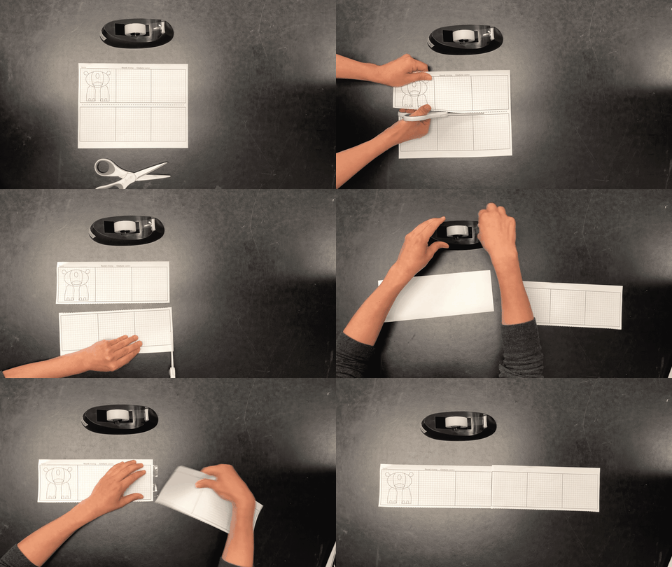
- Cut the paper along the dotted line and tape the two halves end to end.
- In the grid immediately to the right of your alien, use a pen or marker to redraw the alien image to the best of your ability. You are not allowed to erase or correct your drawing. You will be given two minutes to complete your drawing.
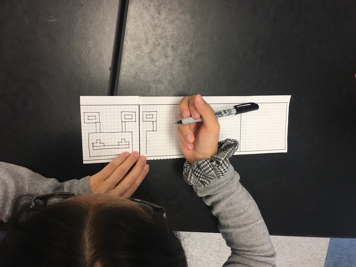
Student making one copy of the alien image. Credit: Andrea LaRosa - After the two minutes, fold the original alien image behind the paper so that only your new drawing can be seen.
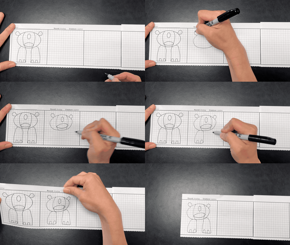
- Pass your paper to your left. Each paper pass represents the message traveling over time and distance. When a new alien is passed to you, don't look at the part folded under.
- In the grid immediately to the right of the redrawn alien, use a pen or marker to redraw the alien image you can see to the best of your ability. Do not erase or correct your drawing. You will be given two minutes to complete your drawing. Fold the alien image you copied behind the paper so that only your new drawing can be seen.
- Repeat steps 4-5 until the alien you originally drew returns to you.
- Analyze the progression of initial image to the last drawing. Record your observations in the Student Observation Sheet.
- Repeat the entire simulation again with the digital round alien images.
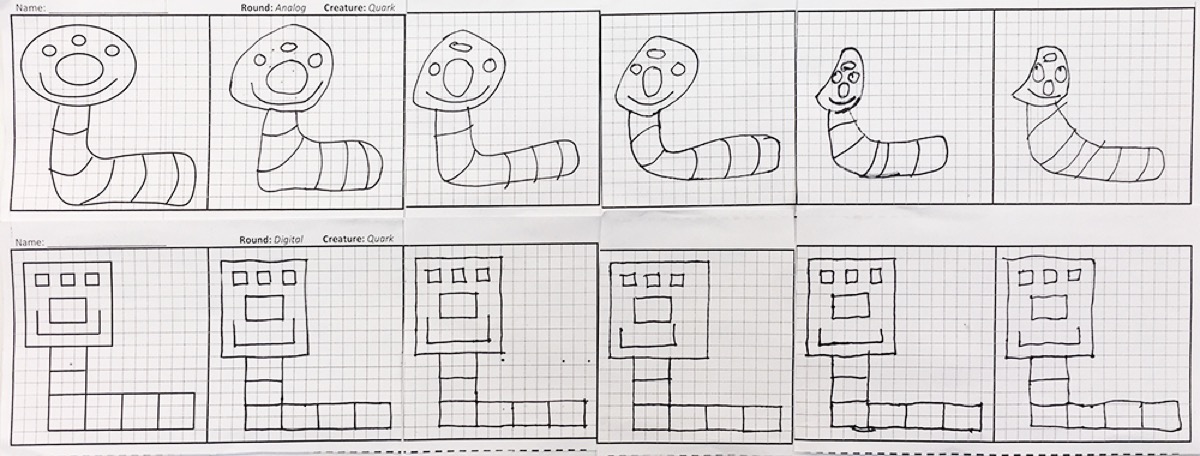
Student-generated progression of alien drawings. Credit: Andrea LaRosa - Be sure to analyze the progression of initial image to the last drawing. Record your observations in the Student Observation Sheet.
Post Activity Questions
(Complete after both analog & digital rounds)
Unfold your alien drawings and observe the images drawn during the activity.
–Compare the original image to the final drawing. Identify and describe the similarities and differences between the two images.
– Observe the progression of drawings during the activity. Identify and describe what changed during each drawing.
Teacher Note: In the analog simulation round, students will observe how tiny changes (distortions/noise) in each copy of the image (signal) result in significant distortion in the final image after multiple transmissions.
Analog And Digital Round Comparison
Compare the images from Round 1 and Round 2 activity.
– Which round resulted in a more accurate final drawing? Support your choice with evidence from the activity.
Teacher Note: In the digital round simulation, the alien images are composed of straight lines that follow the grids on the handout representing how digital signals are composed of quantized , or a limited number of values. When students compare the images they transmitted via analog and digital "signals," they will notice that there is little distortion in the digitally-transmitted image even after multiple transmissions, unlike what they observed when they transmitted the image using an analog signal.
Related Segment
Preventing A 'Digital Dark Age'
Activity 2: Digital and Analog Signal Card Sort
In this activity, students will familiarize themselves with characteristics of digital and analog signals, and apply their characterization to choosing digital or analog storage for a specific example.
Materials
— Scissors
— Digital & Analog Card Sort
— Endangered Bird Song Writing Prompt
— Claims-Evidence-Reasoning Rubric
Teacher Set Up
- Organize the students into groups of three.
- Precut and scramble a set of cards for each group.
- Share the CER Rubric with students.
Student Directions
- Sort the images and statements into two categories: Digital Signals or Analog Signals.
- Use the sorted images and statements to guide your thinking as you complete the writing prompt.
Writing Prompt
Which type of signal would you suggest to record a highly-detailed song of an endangered bird? Support your choice with evidence from your card sort. Use the Claims-Evidence-Reasoning (CER) Rubric to help guide your writing.
Related Educational Resource
The 2019 Science Friday Educator Collaborative
Activity 3: Binary Conversion
In this activity, we'll use binary coding to represent pathways through a series of "high" and "low" choices, which represent which path to take on a logic map. Students will act as digital-analog converters to decode binary pulses, and to create a picture by changing the pulses into colored pixels.
The music transmitted to your car via satellite radio and the information stored in data libraries are both digital signals that use a binary system. In a binary system, there are only two digits, 1 and 0. The value or meaning of these digits can vary. For example, they can represent "true" and "false," "on" and "off," or "high" and "low."
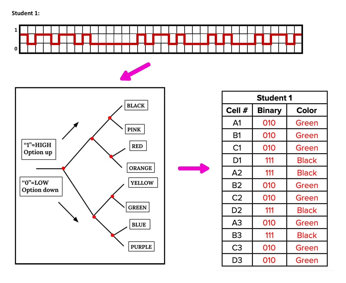
This graphic shows how binary coding can be used to represent pathways through a series of "high" and "low" choices. Following the binary code will guide the path to take on a logic map, and help in finding the intended colors.
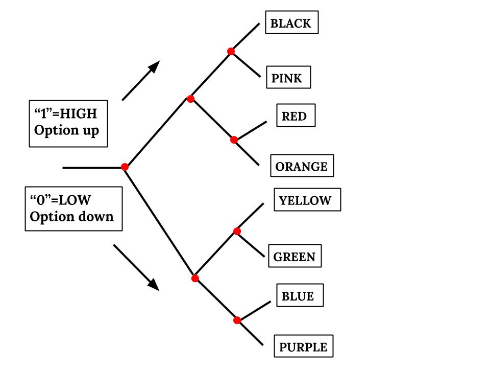
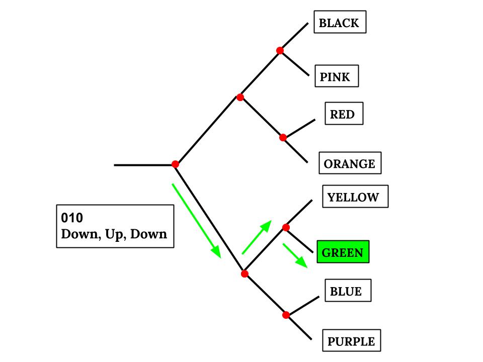
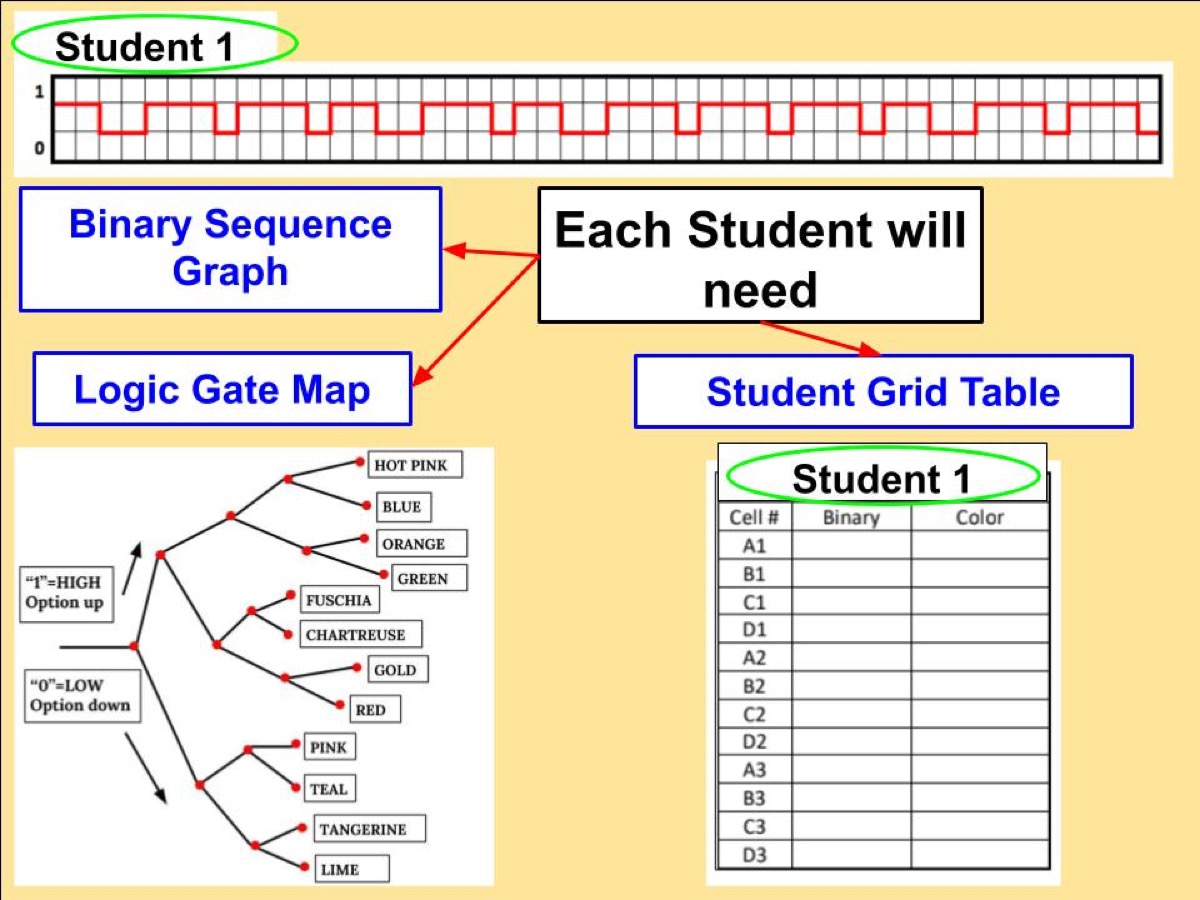
A "1" will indicate to take the "high" path and a "0" will indicate the "low" path. With this map, called a "logic gate map", a binary series of 0's and 1's can indicate when to "go high" or "go low", conveying a path in the map to "code" for a color. For example, using the logic map above, 010 would indicate "0" go down, "1" go up, "0" go down. This will code for the color green.
Now You Try
Use this chart to determine what color would be coded by the number 111?

If you ended at black, you got it!
Digital signals are transmitted to computers in the form of electronic signals sent as pulses. The digital device interprets each pulse's voltage as either a 0 or 1. The image below is an example of a digitized wave.

Using this graph, where the red lines on the top part represent a "1", and the red lines on the bottom part represent a "0", you can see that the entire red line represents the sequence of 1s and 0s along the top of the graph: 11001110111011.
If we were to use each group of three numbers to find a corresponding color on the table above, we would use:
110 – pink
011 – blue
101 – red
Pixels Explained
Most electronics like smartphones, computers, and television screens use liquid crystal display (LCD) technology. The screen is made of millions of tiny pieces called pixels . The electronic device receives coded information, in the form of digital signals, and uses electricity to control the color of the pixels. Each tiny pixel is simply changing from one color to the next depending on the electrical signal, but since the pixels are so small your eye detects movement in the overall image. An amazing example of this in nature, are the scales or "pixels" on a butterfly wing picture below and in this cool video .
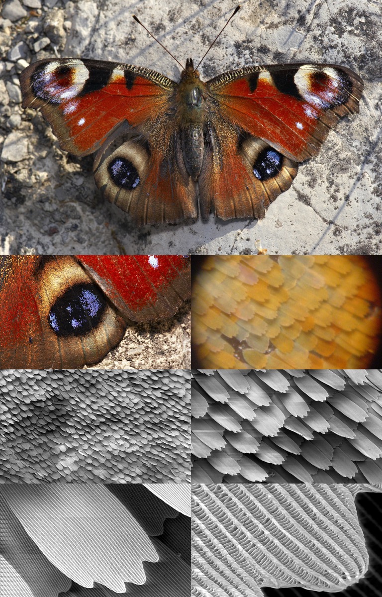
How Does The Activity Work?
Each student is assigned a digital wave graph like the one pictured below. Using the logic gate map, students will decode the signal into the pixel colors for part of the mosaic.
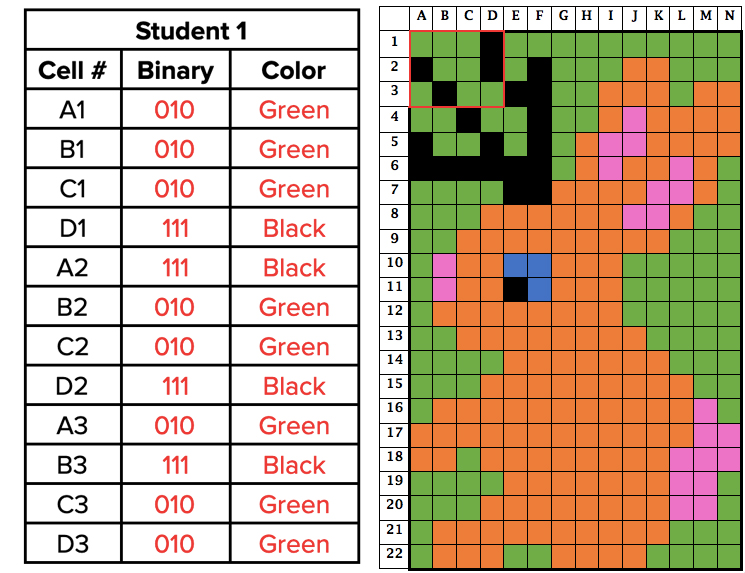
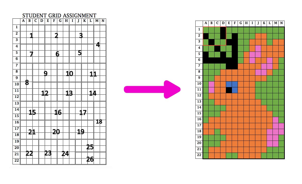
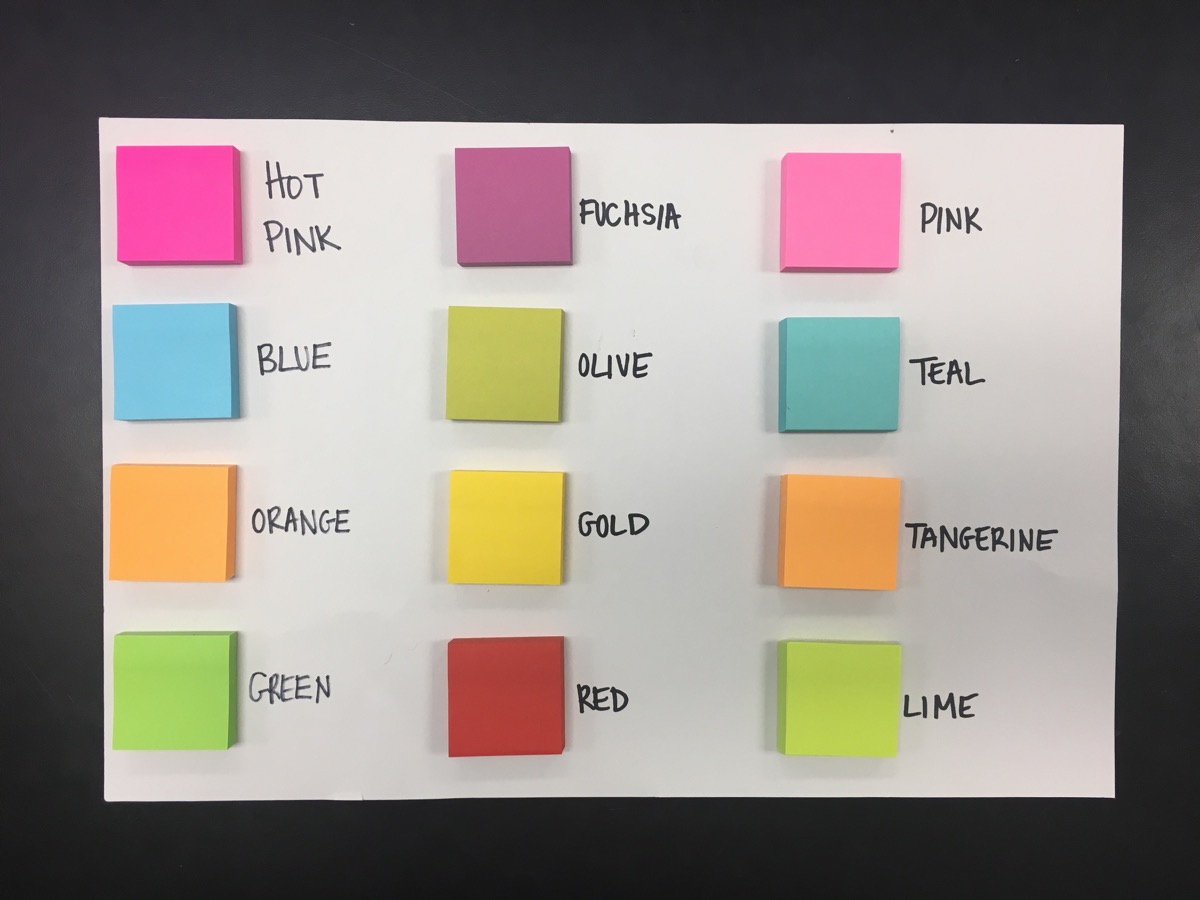
To make your own classroom mosaic masterpiece, four classes complete a panel of a larger Post-it mural.
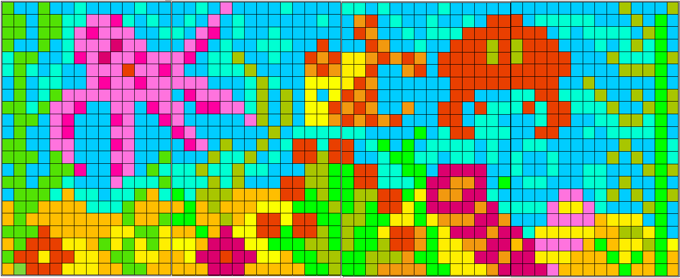
Materials
— Meter stick
— Tape
— Legal size paper, cut in half lengthwise for the grid labels
— Student logic gate map and student grid tables
— Binary sequence graphs
— Eight 22×28 inch poster boards (suggest using two per class):
— 2 x 2-inch Post-it stickies:
— 2 packs Post-it Super Sticky Notes, 2 in x 2 in, Rio de Janeiro Collection
— 1 pack Post-it Super Sticky Notes, 2 in x 2 in, Marrakesh Collection
— 1 pack Post-it Super Sticky Notes, 2 in x 2 in, Bright Neons
— Note to educators: The packs above will make the full mosaic with correct colors (154 Post-it stickies per poster board). If the Post-it stickies are not available, students can color in the grid with markers.
Preparation
Before the students create their Post-it masterpiece, draw a 14 by 11 square grid on each poster board. The rows and columns will both be two inches wide (the width of your stickies). Tape the two poster boards together along the 28-inch sides so that you create a 22 x 11 grid.
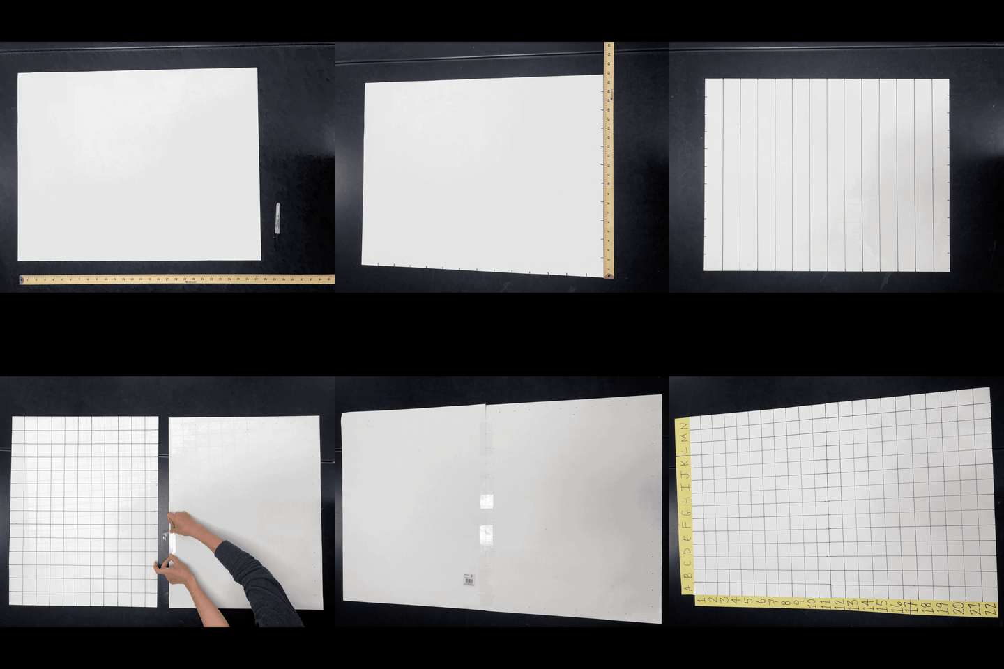
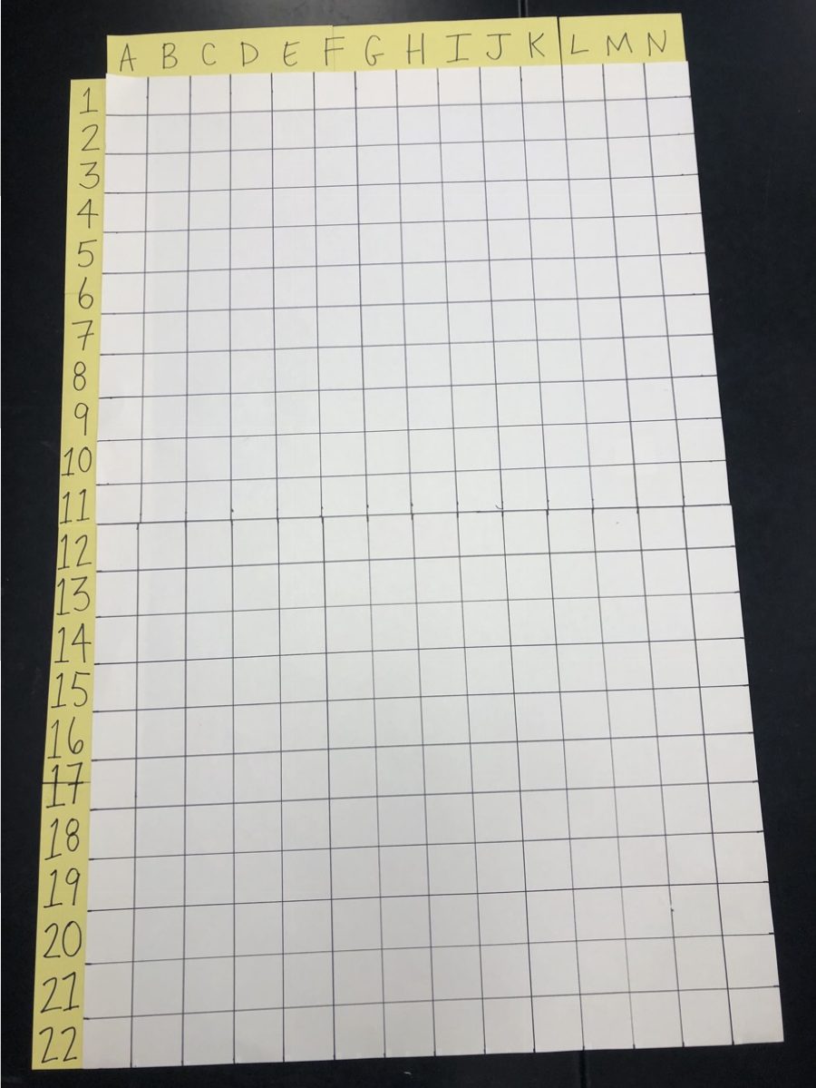
Print out the student binary sequences and grid assignment tables. Cut these sheets along the dotted lines and give each student the assigned sequence and corresponding grid table. Your setup should look like this:
Student Procedure
Decode : You will decode 10-12 squares on the grid. Below is an example of a binary sequence graph. The red line is a digital representation of a signal. Use your assigned signal graph and the logic map to decode the binary sequence and color in your grid table. Check your answers with your teacher before moving onto mosaic construction.

Construct : Get the number and colors of Post-its for your section of the mosaic. Place your stickies onto the corresponding squares in the poster board grid.
Add the Post-its to the poster board grid in the correct order. As you do, think of each square on the grid as a pixel, and your color choice as a result of the processing of the binary code to get the right color!
— What did your class make?
— Do you think you could create a binary code guide to make a mural?
Activity 4: Signal Simulation and Binary Conversion Reflection
Materials
— Signal Simulation and Binary Conversion Reflection
— Writing CER Rubric
Teacher Set Up
- Share the Signal Simulation and Binary Conversion Reflection hand out and CER Rubric with students.
Writing Prompt
— Use the following tables to make a claim for which type of signal, digital or analog, is a more reliable way to encode and transmit information. Provide three pieces of evidence to support your claim from your findings from the signal simulation and binary conversion learning activities.
Table 1: Signal Simulation
| Analog |
|---|
 |
| Digital |
 |
Table 2: Binary Conversion Activity: this data represents the information coded for only 3 students.
| Analog | Digital |
|---|---|
| 11001110111011001100110011101 1001100110011101100111011101 01111011001011010111100101011 10111010111101100101101011110 0101011111011101011110111010111 1011100110110111111101011110111 0101111011100110110111111 | Color cell A1, Green. Color cell B1, Blue. Color cell C1, Blue. Color cell D1, Green. Color cell A2, Green. Color cell B2, Green. Color cell C2, Blue. Color cell D2, Green. Color cell A3, Green. Color cell B3, Green. Color cell C3, Blue. Color cell D3, Green. Color cell E1, Blue. Color cell F1, Blue. Color cell G1, Teal. Color cell H1, Blue. Color cell E2, Green. Color cell F2, Teal. Color cell G2, Teal. Color cell H2, Pink. Color cell E3, Green. Color cell F3, Teal. Color cell G3, Pink. Color cell H3, Hot Pink. Color cell I1, Blue. Color cell J1, Blue. Color cell K1, Blue. Color cell L1, Teal. Color cell I2, Pink. Color cell J2, Hot Pink. Color cell K2, Teal. Color cell L2, Blue. Color cell I3, Pink. Color cell J3, Pink. Color cell K3, Pink. Color cell L3, Blue. Color cell M1 Green. Color cell N1, Blue. Color cell O1, Blue. Color cell P1, Green. Color cell M2, Green. Color cell N2, Green. Color cell O2, Blue. Color cell D2, Green. Color cell A3, Green. Color cell B3, Green. Color cell O3, Blue. Color cell M3, Green. Color cell A11, Blue. Color cell F11, Blue. Color cell G11, Teal. Color cell H11, Blue. Color cell E12, Green. Color cell I12, Pink. Color cell J12, Hot Pink. Color cell K12, Teal. Color cell L12, Blue. Color cell I13, Pink. Color cell J13, Pink. Color cell K13, Pink. Color cell L13, Blue. Color cell A14 Green. Color cell B14, Blue. Color cell C14, Blue. Color cell D14, Green. Color cell A22, Green. Color cell B22, Green. Color cell C22, Blue. Color cell D22, Green. Color cell A23, Green. Color cell B23, Green. Color cell C23, Blue. Color cell D23, Green. Color cell E12, Blue. Color cell F15, Blue. Color cell G15, Teal. Color cell H15, Blue. Color cell E25, Green. |
Educator's Toolbox
Next Generation Science Standards
MS-PS4-3 : Integrate qualitative scientific and technical information to support the claim that digitized signals are a more reliable way to encode and transmit information than analog signals.
Credits
Coding assistance by Luca Fox LaRosa
Mosaic design by Stephanie Near
Editing by Brian Soash and Shirley Campbell
Digital production by Brian Soash, Ariel Zych, Lauren J. Young, and Brandon Echter
Meet the Writer
About Andrea LaRosa
Andrea LaRosa teaches 8th-grade science at Westside Middle School Academy, in Danbury, Connecticut. She is a firm believer in "show one, do one, teach one."
Source: https://www.sciencefriday.com/educational-resources/how-computers-store-information/
Enviar um comentário for "Signals Form Smooth Continuous Waves Unlike Square Digital Waves"